Cummins Coolant Level Sensor 4383933 Wiring Diagram & Complete Diagnostic Guide
Cummins Coolant Level Sensor 4383933 Wiring Diagram & Complete Diagnostic Guide
Does your Cummins vehicle’s dashboard keep showing a coolant level warning even when you check the reservoir and find it full? You’re not alone as this common issue is usually caused by a faulty sensor or wiring problem. This guide will provide you with the exact wiring diagram for 4383933 and show you how to diagnose the fault in 5 simple steps using a multimeter.
1. Understanding the 4383933 Sensor Wiring Diagram
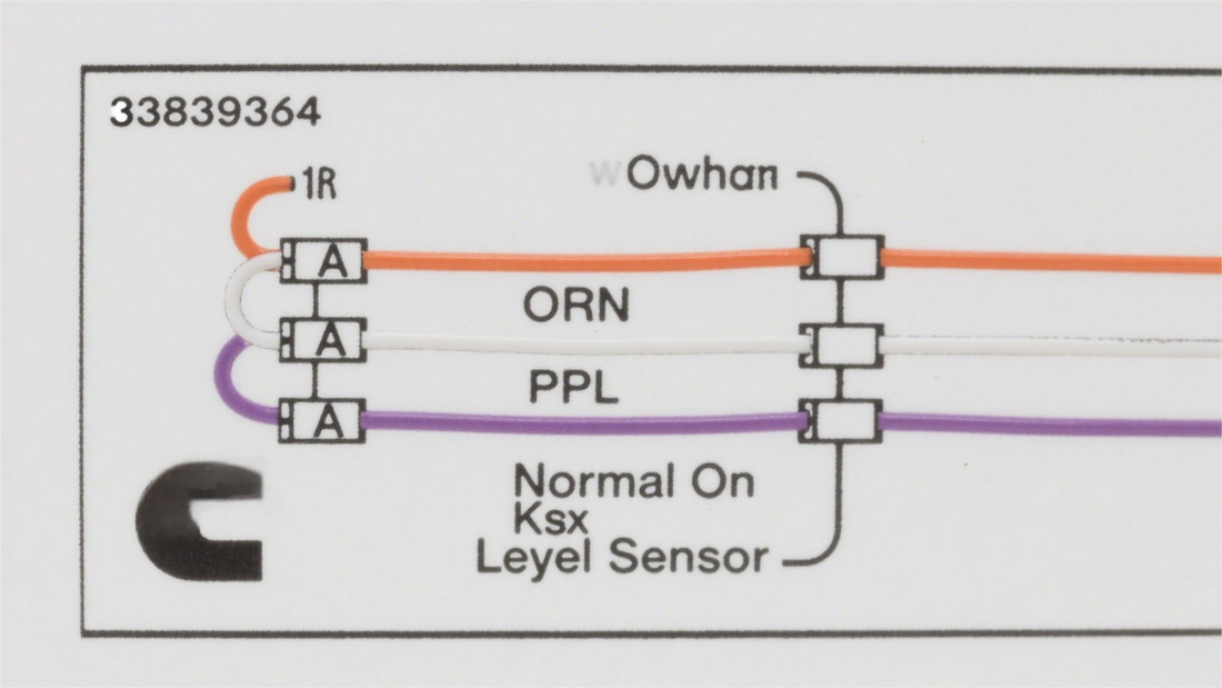
First take a look at a clear official wiring diagram for the Cummins 4383933 coolant level sensor

|
Wire Color / Abbreviation |
Terminal |
Function |
Normal Reading When Key is On |
|
ORN (Orange) |
A |
Power Supply (+5V or +12V) |
Approximately 5V or 12V |
|
WHT (White) |
B |
Signal Feedback to ECM |
Varies with coolant level |
|
PPL (Purple) |
C |
Ground |
0 ohms relative to battery ground |
The 4383933 coolant level sensor typically works on the float and variable resistor principle where the float moves up and down as the coolant level changes, which adjusts the resistance of the variable resistor and in turn changes the signal voltage sent to the ECM so the ECM can determine if the coolant level is normal based on this signal.

2. Step-by-Step Fault Diagnosis Process
Step 1: Visual Inspection of Wiring
Carefully inspect the wiring harness connected to the sensor for signs of wear, burning or corrosion as damaged wiring insulation can lead to short circuits or open circuits while corrosion at the connectors can interfere with current transmission and cause faults—repair or replace the wiring harness promptly if any of these issues are found.

Step 2: Checking Power Wire Voltage
Set your multimeter to DC voltage mode, connect the red probe to sensor terminal A (orange wire) and the black probe to the negative battery terminal then turn the vehicle key to the “ON” position (without starting the engine) and the multimeter reading should be around 5V or 12V. No reading or a significantly deviant reading indicates a problem with the power supply circuit possibly due to an open circuit, blown fuse or faulty power module so further inspection of related components is needed.
Step 3: Checking Ground Wire Resistance
Switch the multimeter to resistance mode, connect the red probe to sensor terminal C (purple wire) and the black probe to the negative battery terminal—normal operation should show a resistance reading close to 0 ohms. A high resistance value means poor grounding which may result from loose connections or rust on the ground circuit so re-tighten the ground connectors or clean any rusted areas.

Step 4: Testing the Sensor Itself
Disconnect the sensor connector, set the multimeter to resistance mode and measure the resistance between the sensor terminals first when the sensor is in a full-liquid level state and then when it is in a low-liquid level state. The resistance should change within a specific range at different liquid levels . An infinite resistance reading (indicating an open circuit) or zero resistance (indicating a short circuit) means the sensor is damaged and needs replacement.
Step 5: Testing Signal Wire Signal
Reconnect the sensor connector and keep the key in the “ON” position then set the multimeter to DC voltage mode, connect the red probe to terminal B (white wire) and the black probe to the negative battery terminal. Artificially adjust the coolant level (such as adding coolant to or draining some from the reservoir) and observe if the multimeter reading changes accordingly—consistent readings mean there may be an open circuit or short circuit in the signal wire or a problem with the signal transmission between the sensor and ECM so check the integrity of the signal wire and the connection of ECM terminals.
3. Frequently Asked Questions (FAQ)
Q1: The sensor has power and ground but no signal feedback—what should I do?
A1: First check if the signal wire (white wire) has an open circuit or short circuit to ground by measuring the continuity of the signal wire section by section with a multimeter. If the signal wire is normal check if the ECM terminals are securely connected and free from looseness or corrosion and reinsert the ECM connector if necessary. If all the above checks show no issues the ECM itself may be faulty and in this case it is recommended to contact professional maintenance personnel for testing and repair.
Q2: Where is the sensor located on the engine?
A2: The Cummins 4383933 coolant level sensor is usually installed on the coolant expansion tank. Locate the coolant expansion tank in the engine compartment (it is generally made of transparent or translucent plastic with liquid level scale marks) and the sensor is typically fixed to the side or top of the tank via threads or clips with several colored wires connected to it making it easy to identify.

We hope this guide helps you diagnose and resolve coolant system faults smoothly. If you have confirmed the sensor is faulty click here to browse our high-quality, reliable and cost-effective replacement Cummins coolant level sensors.